A technique, profession, art, and science of identifying the two-dimensional or three-dimensional positions of objects on the ground, as well as the distances and angles between them, is known as surveying. A land surveyor is an expert in the field of land surveying. These points are typically located on the Earth’s surface and are frequently used to determine a map of the study area and ownership boundaries, areas, such as the designed positions of building components for construction or the surface location of subsurface structures, or other aspects mandated by government or civil law, such as property transactions.
A surveyor is a professional who has the academic credentials and technical skills to do one or more of the following activities:
- to recognize, measure, and represent land, three-dimensional objects, point fields, and trajectories;
- to collect and understand land and spatially related information.
- To utilize the information for planning and effective management of the land, water, and any construction on it; and
- to perform research and development on the aforementioned techniques.
Surveying also includes the technique of creating points using specified angular and linear measurements, which is commonly referred to as surveying. The size and volume of a given piece of land may be determined using the plans, sections, and maps created through surveying. The horizontal projection of the surveyed area, rather than the actual extent, is depicted on a map. Drawing sections, on the other hand, is a better way to depict vertical distance.
Transportation Engineering
Transportation engineering is the use of technologies and scientific concepts in the design, operation, planning, and management of transportation infrastructure, mobility services, traffic, and travelers for various modes of transportation to ensure the safe, efficient, rapid, comfortable, convenient, economical, and environmentally sustainable movement of people and goods.
TYPES OF SURVEYING
Surveying may be divided into two categories.
- Plane Surveying
- Geodetic or Trigonometrical Surveying
Difference Between Plane Surveying and Geodetic Surveying
PLANE SURVEYING
- The Earth’s surface is assumed to be flat.
- Any line produced by two points is termed a straight line, since the identical angles are straight angles.
- suitable for small-area surveying.
- The survey’s precision is low.
- survey method that is both economical and easy.
GEODETIC or TRIGONOMETRICAL SURVEYING
- The earth’s surface is thought to be spherical.
- Any line produced by uniting two points is termed an arch, since the identical angles are spherical angles.
- suitable for large-scale surveying.
- The survey’s precision is high.
- A specialized device is required, as is a lengthy survey method.
PLANE SURVEYING
Plane surveying deals with small areas on the earth’s surface, supposing that the land’s surface is flat. As a result, the earth’s curvature is overlooked. Plane surveying is further classified into the following categories:
Ordinary Leveling determines the elevations of various sites on the earth’s surface. All elevation data required for construction activities is provided.
Plane table surveying is a graphical surveying approach in which field measurements and plotting are done at the same time. It is more straightforward and less expensive than the Theodolite survey, however it is best suited to small-scale surveys.
Traverse surveying is a method of surveying and it is quite widespread. This article discusses the definition and categorization of traverse surveying, as well as traversing mistakes, checks, the finished traversing technique, and traverse survey plotting.
Chain Surveying is a type of surveying that solely takes linear measurements in the field. This is appropriate for surveying small areas with modest features and a somewhat level area. The fact that the chain is the most often utilized piece of equipment gives it its name.
GEODETIC SURVEYING
Surveying that takes into account the real shape of the ground. These surveys are extremely precise and cover enormous areas. Geodetic surveying can be divided into the following categories:
Astronomical Surveying– celestial bodies are used to determine the meridian, azimuth, latitude, longitude, and other parameters of the plot to be surveyed.
Photographic Surveying –photographs taken from appropriate camera stations; the stations can even be airplanes, are being used to create maps. The result is a map, a sketch, or a 3D model of a real-world scene or item.
Reciprocal leveling- is a surveying technique that uses readings from both directions between two places to eliminate mistakes. By calculating the distinction between the two sets of measurements, you can figure out what the leveling error is and what a really level line would be.
Triangulation- is a surveying technique that involves measuring the angles created by three survey control points in a triangle. Each of the computed distances is then used as one of the sides of a new triangle to calculate distances to a new point, which may then be used to start a new triangle.
Tacheometry or Stadia Surveying –is a branch of angular surveying in which the horizontal and vertical distances between locations are measured using optical techniques rather than the more time-consuming tape or chain method.
Six of the most common instruments for surveying
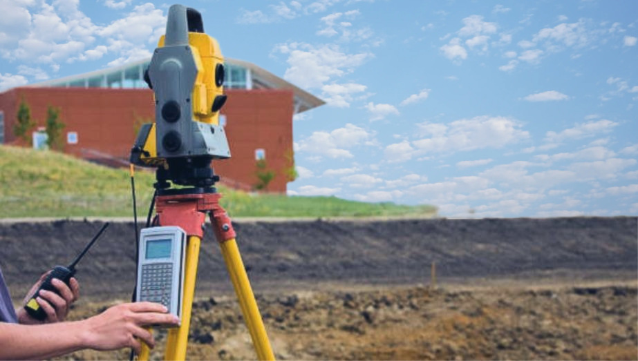
Total station: A total station is a theodolite with an on-board computer for data collection and triangulation computations that employs electronics to calculate angles and distances. This tool is used in topographic surveying to record features or to lay out features (roads, buildings, or boundaries).
3D Scanner:3D scanners are surveying devices that can measure and capture data from objects, surfaces, structures, and landscapes with pinpoint accuracy. This tool gathers data in the form of point cloud data, which is made up of millions of three-dimensional coordinates. These coordinates may be used to construct 3D CAD models, which can subsequently be used to examine terrain features and structures. The excellent precision of 3D scanners aids in project cost reduction.
GPS/GNSS: The use of Global Positioning System (GPS) and/or Global Navigation Satellite System (GNSS) signals through a receiver and antenna to identify a shape, boundary, position, object, or point in space in relation to other shapes, boundaries, or points. Using on-demand centimeter-level precision given by Real-Time Kinematic (RTK) positioning, this technology has substantially boosted surveyors’ speed and productivity.
Theodolite: A surveying tool with a spinning telescope for measuring horizontal and vertical angles and triangulating the position of objects in a defined area.
Measuring Tape: A measuring tape is a length of tape or thin flexible metal with intervals marked on it for measuring size or distance. Surveyors frequently use tape measures (also known as measuring wheels) to measure distances of more than 100 meters.
SURVEYING FORMULAS
Simple Curve
A simple curve is made out of a single arc of a circle joining two straights. It has a radius of the same magnitude throughout.
Tape MeasurementStadia MeasurementSubtense BarReduction to sea levelEffect of curvature
Simple Curve Terminologies
- PC= Point of curvature, beginning of curve
- PT= Point of tangency, end of curve
- PI= Point of intersection of tangents
- T= Tangent length from PC to PI and PI to PT, It’s called a “sub-tangent.”
- R=A simple curve’s radius, or simply radius.
- L= chord length from PC to PT. The midpoint of L is represented by point Q in the diagram.
- Lc= The length of the curve from PC to PT. The figure’s point M represents the middle of Lc.
- E= External distance, the shortest distance between PI and the curve.
- m= The middle ordinate is the distance between the midpoints of the curve and the chord.
- I= Deflection angle (also known as intersection angle or center angle). It’s the tangents’ intersection angle. The angle formed by PC and PT at O is also equal to I, where O is the circular curve’s center.
- x= offset distance from the curve’s tangent T is perpendicular to x.
- θ=PC’s offset angle between PI and any point on the curve
- D= Degree of curve. One station equals 100 feet in the English system and 20 meters in the SI system
- Sub chord =The chord length between two adjacent complete stations.
Sharpness of Circular Curve
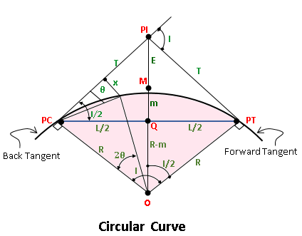
The curve becomes flatter as the degree of curvature decreases, and vice versa. R is also used to determine the sharpness of a basic curve. The difference between a large and small radius is that the large radius is flat and the tiny radius is sharp.
Length of tangent, T
The length of tangent (also known as subtangent) is the distance between PC and PI. The distance between PI and PT is the same. Using the right triangle PI-PT-O ,

External Distance, E
The external distance is the distance between PI and the curve’s midpoint. From the same PI-PT-O right triangle,

Middle Ordinate, m
The middle ordinate is the distance between the curve’s and chord’s midpoints. O-Q-PT is the right triangle.

Length of Long Chord, L

The distance between PC and PT is measured by the length of a long chord. From the right triangle, O-Q-PT
Length of Curve, Lc
The road distance between the endpoints of a simple curve is the curve length from PC to PT. Using proportion and ratio.

Another way to calculate the length of a curve is to use a ratio and proportion to the curve’s degree of curvature.
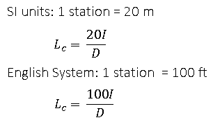
If given the stationing of PT and PC
Lc = Stationing PT – PC
Degree of Curve, D
The central angle subtended by an arc (arc basis) or chord (chord basis) of one station is defined as the degree of curvature. It will determine the curve’s sharpness.1 station equals 20 meters in SI. It is vital to remember that 100 feet is equal to 30.48 meters, not 20 meters. In the English system, one station equals 100 feet.
Arc basis
1 station/D = 2πR/360°
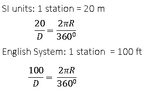
Chord Basis
sin D/2 = half station/R
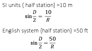
Compound Curve
A compound curve is made up of two or more simple curves with distinct centers that bend in the same direction, are on the same side of their common tangent, and link to form a continuous arc. The point of compound curvature is the intersection of two curves (that is, the point at which the PT of the first curve equals the PC of the second curve) (PCC).
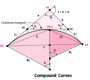
Finding the PT station
Given PC’s station,
Sta PT = Sta PC + Lc1 +Lc2
Given PI’s station,
Sta PT=Sta PI−x−T1+Lc1+Lc2
Compound Curve Elements
- PC = point of curvature
- PT = point of tangency
- PI = point of intersection
- PCC = point of compound curve
- T1 = length of the first curve’s tangent
- T2 = length of the second curve’s tangent
- V1 = first curve’s vertex
- V2 = second curve’s vertex
- I1 = first curve’s central angle
- I2 = second curve’s centre angle
- I = intersection angle = I1 + I2
- Lc1 = first curve length
- Lc2 = second curve length
- L1 = first chord length
- L2 = second chord length
- L = long chord length from PC to PT
- T1 + T2 = common tangent length measured from V1 to V2.
- θ = 180° – I
- Triangle V1-V2-PI may be used to find x and y.
- L may be found using the triangle PC-PCC-PT.
Reverse Curve
A reverse curve is formed by two successive tangent curves with radius points on opposite sides of the center line.
Finding the PT station
Given PC’s station,
Sta PT=Sta PC + Lc1+Lc2
Given V1 station,
Sta PT=Sta V1−T1+Lc1+Lc2
Reversed Curve Elements
- PC= point of curvature
- PT= point of tangency
- PRC= point of reversed curvature
- T1= length of tangent of the first curve
- T2= length of tangent of the second curve
- V1= vertex of the first curve
- V2= vertex of the second curve
- I1= central angle of the first curve
- I2= central angle of the second curve
- Lc1= length of first curve
- Lc2= length of second curve
- L1= length of first chord
- L2= length of second chord
- T1+ T2 = length of common tangent measured from V1 to V2
SPIRAL CURVE
A spiral is a changing radius curve that is used to progressively increase the curvature of a road or railroad. Spiral curves are generally utilized to prevent skidding and steering issues by providing a gentle transition between straight-line and turning action, as well as to provide a way of effectively super elevating curves.
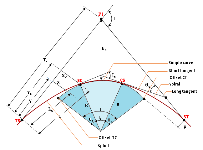
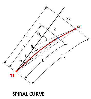
- e curve
SPIRAL CURVE ELEMENTS
- TS= Tangent to spiral
- SC= Spiral to curve
- CS= Curve to spiral
- ST= Spiral to tangent
- LT= Long tangent
- ST= Short tangent
- R= Radius of simple curve
- Ts= Spiral tangent distance
- Tc= Circular curve tangent
- L= Length of spiral from TS to any point along the spiral
- Ls= Length of spiral
- PI= Point of intersection
- I= Angle of intersection
- Ic= Angle of intersection of the simple curve
- p= Length of throw or the distance from tangent that the circular curve has been offset
- X= Offset distance (right angle distance) from tangent to any point on the spiral
- Xc= Offset distance (right angle distance) from tangent to SC
- Y= Distance along tangent to any point on the spiral
- Yc= Distance along tangent from TS to point at right angle to SC
- Es= External distance of the simple curve
- θ= Spiral angle from tangent to any point on the spiral
- θs= Spiral angle from tangent to SC
- i= Deflection angle from TS to any point on the spiral, it is proportional to the square of its distance
- is= Deflection angle from TS to SC
- D= Degree of spiral curve at any point
- Dc= Degree of simpl
Spiral Curve Formulas
Distance from any point on the spiral along tangent
The distance from the tangent to any point on the spiral offset is:
Throwing distance:
Spiral angle in radians measured from the tangent to any point on the spiral:
From TS to any point on the spiral, the deflection angle is:
The square of the angle’s distance is proportional to it.
Tangent distance
Simple curve intersection angle:
External distance
The spiral curve’s degree
Parabolic Curve
Parabolic curves are used to connect portions of roadways or railroads with varying gradients. A parabolic curve is used to give a progressive shift in direction along the curve.
Parabolic Curve in the Vertical Direction
Vertical curves are used to offer a smooth transition between two neighboring vertical grade lines. A parabola curve connects the two neighboring grades. Because the second derivative of a parabola is constant, it allows for a smooth transition. The conventional equation for a descending parabola with an origin vertex is
The first derivative is the slope of the curve, as you may recall from calculus.
Since y’ is linear, the grade diagram (slope diagram) for a summit curve is downward and linear, as shown by the illustration. The rate of change of slope is understood as the second derivative, which is plainly constant. Because of this property, the parabola is a desirable curve because it provides a constant rate of change of slope.
Vertical Curve Elements
- PC= point of curvature, also known as BVC (beginning of vertical curve)
- PT= point of tangency, also known as EVC (end of vertical curve)
- PI= point of intersection of the tangents, also called PVI (point of vertical intersection)
- L= length of parabolic curve, it is the projection of the curve onto a horizontal surface which corresponds to the plan distance.
- S1= horizontal distance from PC to the highest (lowest) point of the summit (sag) curve
- S2= horizontal distance from PT to the highest (lowest) point of the summit (sag) curve
- h1= vertical distance between PC and the highest (lowest) point of the summit (sag) curve
- h2= vertical distance between PT and the highest (lowest) point of the summit (sag) curve
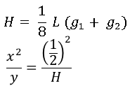
- g1= grade (in percent) of back tangent (tangent through PC)
- g2= grade (in percent) of forward tangent (tangent through PT)
- A= change in grade from PC to PT
- a= vertical distance between PC and PI
- b= vertical distance between PT and PI
- H= vertical distance between PI and the curve
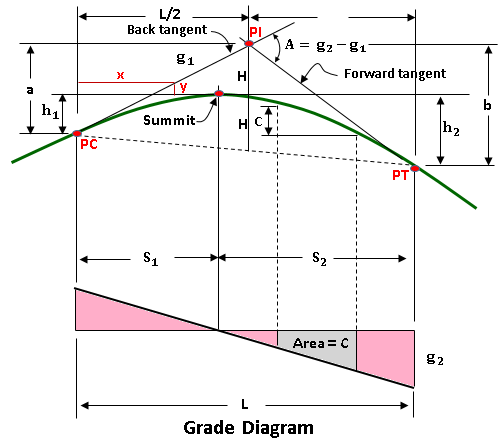
The image shown depicts the geometric characteristics of a parabolic curve.
Parabolic Curve Properties and Grade Diagram
- The horizontal distance between PI and PT defines the length of the parabolic curve L.
- The PI is situated between the PC and the PT.
- The curve is located midway between PI and the chord’s midpoint from PC to PT.
- The vertical distance between any two locations on the curve equals the area under the grade diagram. The vertical distance c = area.
- The grade of the curve at a given location equals the offset distance in the grade diagram under that point. The point total. The point total at g is equivalent to the point Q.
The ideas and formulae may be used on both sag and summit curves.
rise = run x slope
Neglecting the sign of g1 and g2
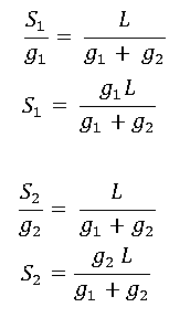
Vertical distance equals the area beneath the grade diagram.
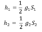
Other equations
